|
I am unemployed at the moment, but I'm very busy. I tend to work
late nights and wander over to bed when I run completely out of
steam. The problem is that this happens at a different time every
day. I end up being too lazy and stupid to re-set the alarm clock,
so I don't bother. I oversleep. Recently I realized that I need a
special alarm clock that instead of going off at a particular time
goes off after a set duration. Like an egg timer, but grand!.
So, I made one, and I realized that it would be a great
beginner’s project. I could have
added things like a snooze feature or a variable time span, but I
opted to keep it simple. If you want something much more
complicated, you can try my MP3 player
project. Or add some crazy stuff to this one. This is also
easily adapted to other timing and control projects.
Operation:
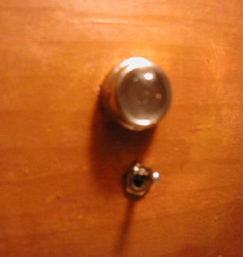
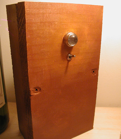
To use the clock, flip the switch to “on” and get in bed. The LED
will blink once each second to let you know it’s working. Go to
sleep. When the alarm goes off get up and flip the switch to “off”.
It’s a new day!
Construction:
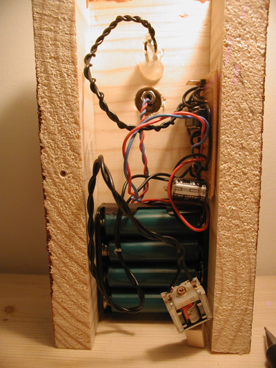
The most fun part is the thing that actually makes the noise. I
used a motor from a small toy and a strip of aluminum. I attached a
small bit of wood to the shaft of the motor and glued the motor to
the strip of metal so that the bit of wood smacks into it. It
makes a really remarkably annoying sound. I also tried placing the
motor in an old glass jar. You could try a cowbell, or a cymbal, or
anything really.
Not much else to say here, other than that you should try things
out on a breadboard first, and that if it doesn't work, 90% chance
that it’s a soldering mistake. Oh, by the way: I tested the code. It
works. Really.
Code:
Here’s
the C code, the schematic and the hex file. The C is the source
code, which you can modify to your heart’s content, the hex file is
what the compiler makes from the C code.
Question? I can be reached here: raphael@walrus.com
|