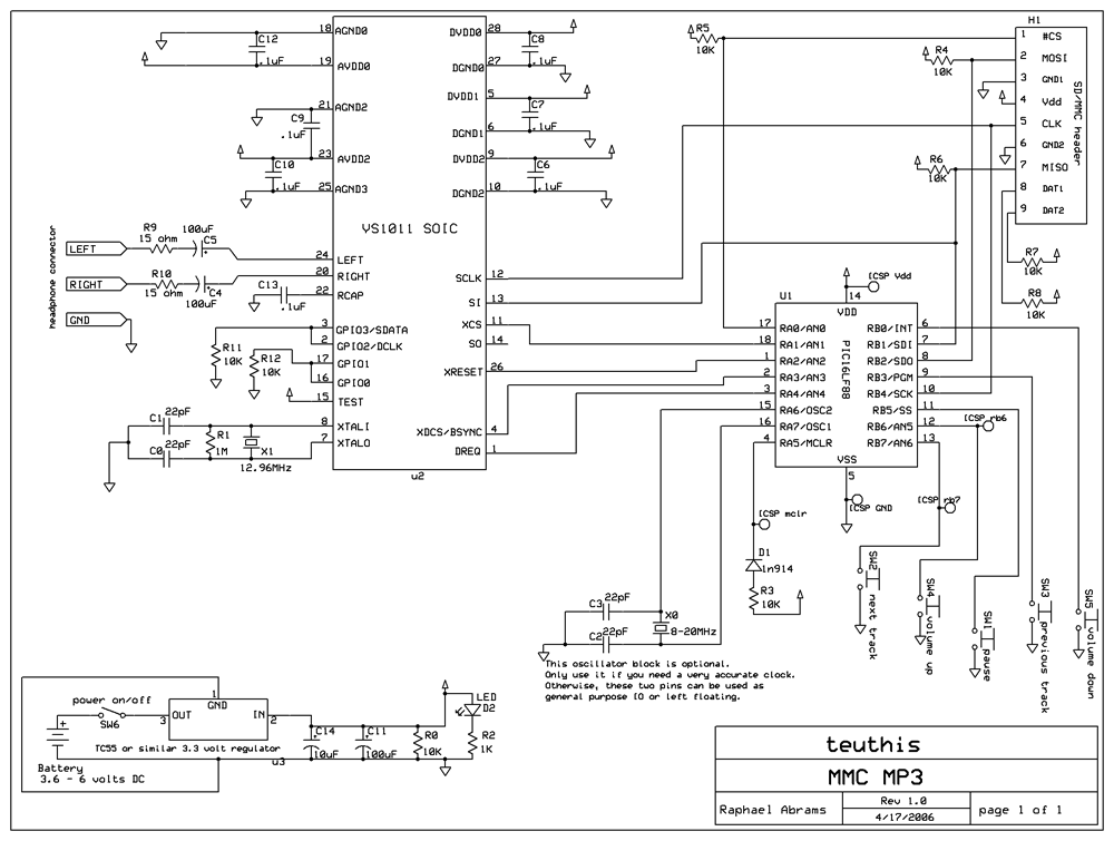
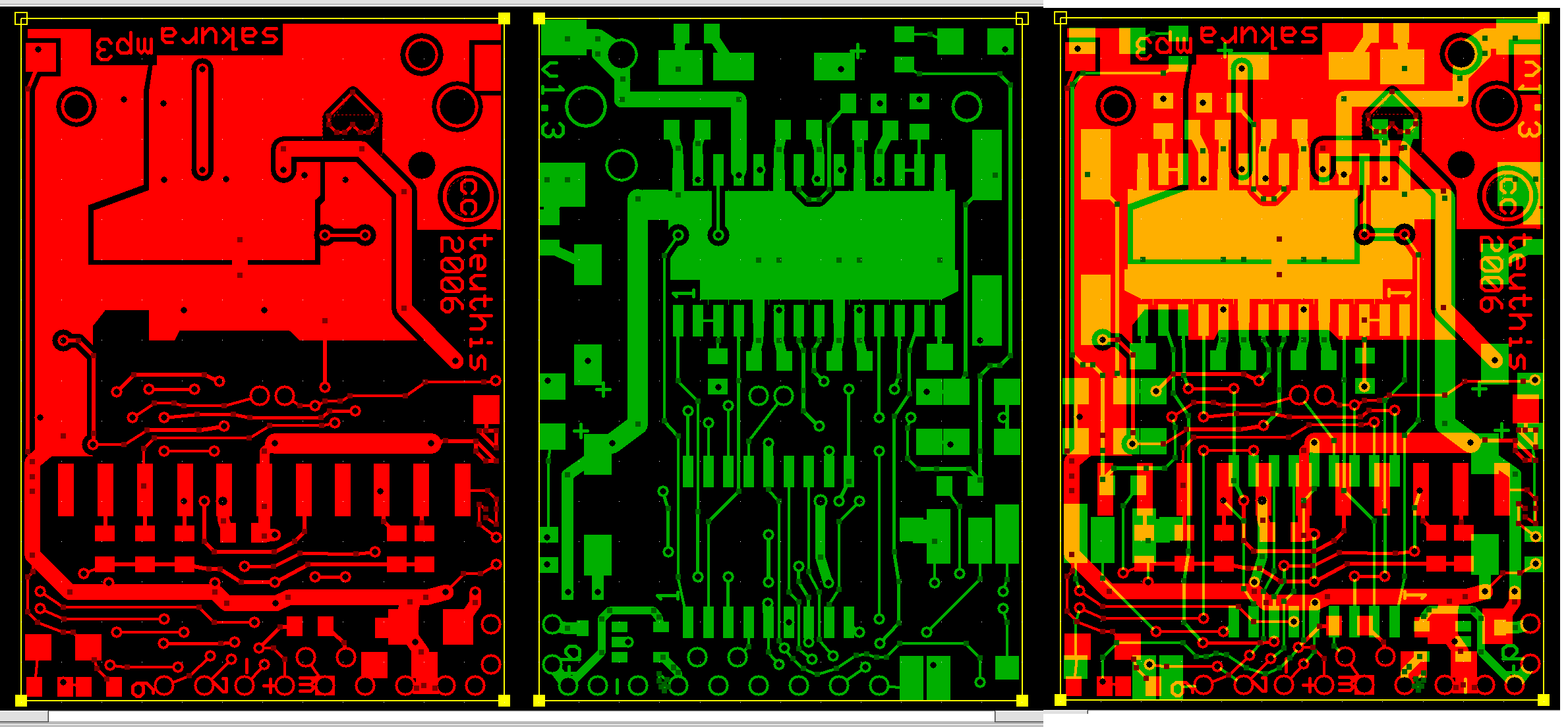
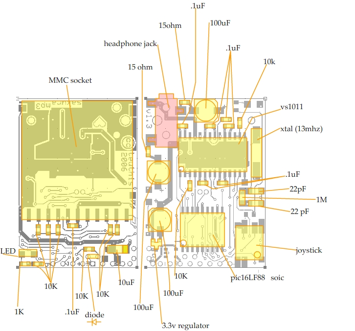
For around $30 in parts and a good amount of patience, you can have a completely open source and hackable mp3 player ready to go. It can be modified to accept serial commands, be embedded in an art project, used as the voice of your next smart talking robo-sidekick, or filled with music and used as is. Put in whatever size card you want, up to the theoretical limit of the MMC format! All the source and schematics are here for free as part of the Creative Commons. I have kits available if you donít feel like scavenging for the parts yourself. This player features a shuffle mode, basic track navigation, volume control, FAT32 support, fragmented file support, an unlimited number of files on the root directory, and high quality playback. Files at 256Kbps can be played without a hitch. Variable bitrate files are supported with peaks up to 320Kbps. WAV files are also supported, but they have to be less than CD quality unless you put a faster oscillator in the pic. It works on my test device, but running the pic at over ~8MHz with only a 3.3 volt supply can be problematic. So I hear. Iím still working on the WAV stuff, so if you have some funny results playing WAV files, let me know. To load the memory card, you will need some sort of card reader/writer. Many computers have them built in. External USB models are available for ~$10. Make sure to format the card FAT32, not FAT16. For normal playback, load a card up with MP3 files (make sure they all have a ď.mp3Ē file extension) and insert it into the player. Turn on the power and it should immediately start playing the first track. Tracks are played in the order that they are put onto the memory card. To get into shuffle mode, hold the ďnext trackĒ button down while you power on the device. It will remain in shufle mode until the next power cycle. Once all the songs have played once (and only once) it will go to sleep until the next power cycle. Please Email me if you have any specific questions, or just to let me know you are doing this project! BEGINNERS BEWARE! This is an intermediate level project. You will need things like a PIC programming device and some working knowlege of C programming, as well as a decent but not huge amount of electronics experience. An oscilloscope doesnít hurt either. Be warned! And the parts are tiny! If you are a beginner, give these books and websites a look: www.parallaxinc.com www.sparkfun.com www.microchip.com www.microchipc.com www.dontronics.com www.jameco.com ccsinfo.com (the midrange compiler is the one I used for this project) all the Forrest Mims III books, available at radio shack Practical Electronics for Inventors, by Paul Scherz and Nuts and Volts Magazine (tower books has it most of the time) Why is it called Sakura? Itís spring here and the cherry blossoms are blooming everywhere. Sakura means cherry blossom in japanese. And the first prototype was housed in a pink plastic box. |


